Leave Your Message

How to Choose the Right Power System Generator?

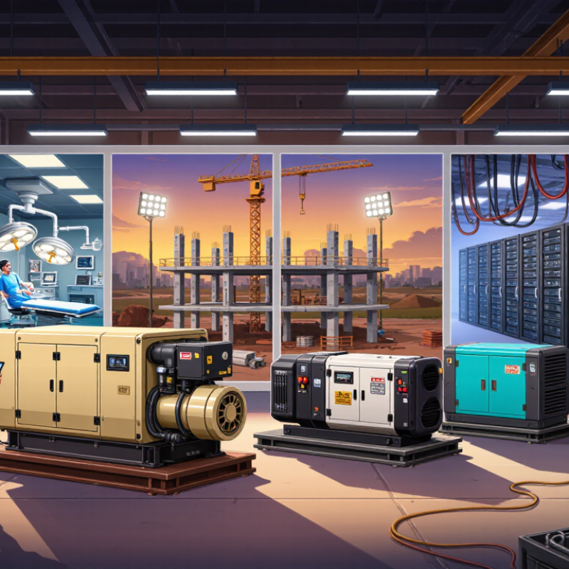
Choosing the right Power System Generator begins with the load, not the machine’s advertised capacity. A shiny enclosure cannot compensate for poor planning. The generator must match the facility’s starting currents, operating voltage, frequency, and required runtime. A hospital, construction site, data center, and rural workshop face very different risks.

Power-systems authority Dr. John D. McDonald describes the scale of the challenge: “The electric power system is the largest machine ever built.” His observation matters because every generator operates within a wider electrical network. Fuel quality, transfer equipment, grounding, protection, and maintenance all influence dependable performance. Ignoring one detail can weaken the entire installation.

Begin with a realistic load survey. Record motors, pumps, compressors, heaters, lighting, and sensitive electronics. Note which loads start together. A 100-kilowatt motor may demand far more power during acceleration. That short surge can trip an undersized unit before normal operation begins.

Fuel selection also requires practical judgment. Diesel generators often suit heavy-duty applications and long operating periods. Natural gas can reduce on-site fuel storage, but supply interruptions remain possible. Hybrid systems may lower fuel use, though their controls require skilled integration. The cheapest purchase can become the most expensive choice.

Consider noise, emissions requirements, weather exposure, service access, and spare-parts availability. Ask who will respond at midnight. That answer is important.

There is no perfect specification sheet. I have seen projects focus on rated output while overlooking ventilation, harmonics, or battery temperature. Those oversights are easy to prevent, but only when engineers examine real operating conditions. A reliable Power System Generator should provide capacity, resilience, safe control, and maintainable performance for its intended environment.

How to Choose the Right Power System Generator?

Define Load Profile, Peak Demand, and 20–30% Generator Capacity Reserve

How to Choose the Right Power System Generator?

Define Load Profile, Peak Demand, and 20–30% Generator Capacity Reserve

A reliable generator starts with the load profile, not the largest machine available. Record electrical demand throughout a normal day, week, and season. Note refrigeration cycling, pumps, compressors, lighting, and motor-starting currents. The U.S. Energy Information Administration’s hourly demand data shows clear differences between commercial, residential, and industrial consumption patterns. A flat industrial load needs different sizing than an office building peaking at 3 p.m.

Peak demand is the highest measured operating load, including realistic starting events. Suppose a facility reaches 180 kW during testing. Adding a 20–30% capacity reserve produces a planning range of 216–234 kW. This reserve supports modest expansion, voltage stability, and unexpected load changes. It is not a universal law. Large motors, high altitude, hot temperatures, and poor power factor can require additional engineering. A 20% margin may be too small.

The International Energy Agency’s Electricity 2024 report estimates data centers used about 460 TWh globally in 2022, with demand potentially exceeding 1,000 TWh by 2026. That growth makes accurate load measurement more important. Engineers should verify both prime and standby ratings, then review fuel autonomy and transfer performance. I have seen sizing decisions rely on nameplate totals alone. That approach looks precise, but it can miss short, severe starting surges. Recheck the assumptions. Load behavior is often less predictable than the spreadsheet suggests.

Classify ISO 8528-1 Ratings: ESP 200 Hours/Year and PRP 70% Average Load

How to Choose the Right Power System Generator?

ISO 8528-1 separates emergency standby power (ESP) from prime power (PRP). ESP is designed for outages, testing, and limited operation, normally up to 200 hours per year. It should not carry continuous loads or routine peak shaving. A 500 kW ESP set may support an emergency panel, but frequent operation can expose a poor application decision. Check local regulations and the manufacturer’s duty limits.

PRP supports variable loads for unlimited running hours. Its average load should not exceed 70% of the rated prime power during any 24-hour period. For a 500 kW PRP set, that means a 350 kW average, although short higher-load periods may occur. Measure real demand, not only connected load. Site commissioning data often reveals motors, pumps, and battery chargers starting together. That detail matters.

The Uptime Institute Global Data Center Survey 2024 reported power problems as the cause of 54% of respondents’ most recent outages. The IEA’s Electricity 2024 report estimated data centers used about 460 TWh globally in 2022, potentially exceeding 1,000 TWh by 2026. Growing demand makes duty classification less forgiving. Still, the 70% rule is not a design target. Leaving no margin can create thermal stress, wet stacking, and unstable transient response. A load study should include starting currents, seasonal demand, test schedules, and future expansion. Mistakes remain possible. Review the rating after commissioning.

Size Motor-Starting Capacity for 5–7× Full-Load Current Inrush

How to Choose the Right Power System Generator?

Motor starting is often the hardest generator-sizing test. An across-the-line induction motor can draw five to seven times its full-load current during startup. A 40-ampere motor may briefly demand 200–280 amperes. That surge can pull generator voltage down, causing contactors to chatter or controls to trip.

Do not size only from running kilowatts. NEMA MG 1 identifies locked-rotor characteristics through motor code letters, while IEEE Std 446 discusses voltage and frequency performance in emergency power systems. These references support a more practical assessment. Record each motor’s full-load current, starting method, acceleration time, and load sequence. Then check the generator’s motor-starting kVA, not merely its standby rating. Field measurements matter. Real sites rarely behave like spreadsheets.

Start the largest motor first.

A softer starter or variable-frequency drive can reduce inrush, but it may introduce harmonics and require compatible controls. The U.S. Department of Energy has reported that motor-driven equipment represents a major share of industrial electricity use, making efficient starting valuable beyond generator protection. Still, the 5–7× estimate is only a screening figure. High-inertia fans, pumps, and compressors may need longer acceleration and greater transient support. I have seen an apparently adequate generator struggle because several motors started together. The calculation was correct, but the sequence was not. Verify assumptions with a load-bank test and actual starting measurements whenever possible.

Match Voltage, Phase, and 50/60 Hz Frequency to Facility Requirements

How to Choose the Right Power System Generator?

Choosing a power system generator starts with the facility’s electrical requirements. Voltage, phase, and frequency must match the equipment, not just the outlet labels. A generator rated for 480 volts may damage loads designed for 400 or 415 volts. I have seen projects focus on kilowatts while overlooking phase compatibility. That mistake becomes expensive.

Single-phase equipment needs a different arrangement from three-phase motors, pumps, and compressors. Check the nameplate voltage and confirm whether the system requires a neutral connection. Motor-driven loads also demand extra starting power. A generator that supports running wattage may still fail during startup. Allow practical headroom, especially when several motors start together. Do not guess here.

Frequency is equally important. Most facilities operate at either 50 or 60 Hz. Frequency affects motor speed, transformer behavior, timing devices, and sensitive controls. A 60 Hz motor supplied at 50 Hz may run slower and draw different current. Some equipment tolerates both frequencies, but only when its specifications clearly allow it. Review every critical load, including imported machinery and control panels.

During selection, compare the generator output with the facility distribution board, transfer equipment, and grounding plan. Verify voltage regulation under changing loads. Test the system with realistic operating conditions, not only a light load. I prefer recording phase voltage, frequency, and startup performance during commissioning. Even careful calculations can miss a nuisance trip. A qualified electrical professional should review the final design and local installation requirements.

Specify NFPA 110 Type 10 ATS Transfer Within 10 Seconds

How to Choose the Right Power System Generator?

Selecting a generator starts with the required emergency load, not the largest available engine. List critical equipment, starting currents, voltage, phase, and future expansion. A pump may draw several times its running current when it starts. Ignoring that detail can cause voltage dips and nuisance shutdowns. For emergency applications, NFPA 110 Type 10 requires the automatic transfer switch to transfer the emergency load within 10 seconds after normal power loss. The generator, controls, fuel supply, and ATS must work as one system. A fast ATS cannot compensate for a generator that starts slowly.

Tips: Confirm the 10-second sequence during commissioning. Test the complete system under realistic load. Record start time, transfer time, voltage, and frequency. Check battery condition, coolant temperature, fuel quality, and alarm signals. Keep clearance around the ATS for inspection and maintenance. Small installation details matter.

An ATS should match the generator voltage, phase, ampere rating, and available fault current. Its sensing settings also need careful adjustment. A setting that is too sensitive may transfer during a brief disturbance. A delayed setting may miss the required response time. NFPA 110 compliance depends on the complete emergency power system, not one component alone. In practice, teams sometimes focus heavily on generator size and overlook cable lengths or weak batteries. That is an avoidable mistake. Still, every site behaves differently, so the final design should be reviewed by qualified electrical professionals and verified through documented testing.

How to Choose the Right Power System Generator? — Specify NFPA 110 Type 10 ATS Transfer Within 10 Seconds
Selection Area What to Specify Why It Matters
Required Performance NFPA 110 Type 10 emergency power performance Specify an emergency power supply system designed and tested to achieve the required emergency power availability within 10 seconds after loss of the normal power source. Coordinate the generator, controls, circuit breakers, and automatic transfer switch as one system. Confirm compliance through system documentation, commissioning records, and a witnessed functional test.
Automatic Transfer Switch ATS transfer time Use an automatically initiated transfer sequence with adjustable engine-start delay, transfer delay, retransfer delay, and emergency-source stabilization settings. The complete emergency power sequence must meet the required 10-second performance target. Do not evaluate ATS transfer time alone; measure the time from normal-source failure to acceptable emergency power at the load.
Load Assessment Connected, starting, and future loads Prepare a load schedule covering continuous loads, motor-starting currents, heating loads, lighting, controls, battery chargers, elevators, pumps, and planned expansion. Include both kilowatts (kW) and kilovolt-amperes (kVA). Size the generator for the largest credible operating and starting combination, not only the total running load.
Capacity and Rating Standby generator rating Select a standby-rated generator with sufficient kW, kVA, voltage, phase, frequency, and short-circuit capability for the emergency distribution system. Avoid operating continuously at the equipment’s maximum rating. Check the manufacturer’s rating definitions, allowable step-load acceptance, voltage dip, frequency dip, and recovery performance.
Voltage and Phase Electrical compatibility Match the generator and ATS to the facility’s normal distribution: voltage, phase configuration, frequency, grounding method, neutral arrangement, and available fault current. Confirm compatibility with service equipment, distribution panels, protective devices, and sensitive electronic loads.
Fuel Selection Fuel availability and storage Choose a fuel system that can operate during the expected outage duration and comply with local storage, ventilation, fire-safety, and environmental requirements. Common options include diesel, natural gas, and propane. Evaluate fuel reliability during disasters, fuel quality, refill logistics, ambient temperature, and required on-site autonomy.
Starting System Reliable automatic starting Provide an automatic starting system with properly sized batteries, a battery charger, engine jacket-water heating where required, and monitored starting-system alarms. Test cold starting, low-battery alarms, charger failure alarms, overspeed protection, and repeated start attempts.
Load Prioritization Emergency and legally required loads Separate critical loads by emergency function and use multiple ATS units or a properly coordinated distribution system when different loads require different transfer priorities. Verify that nonessential loads cannot overload the generator or delay power restoration to critical loads.
Installation Environment Indoor or outdoor operating conditions Account for altitude, ambient temperature, humidity, ventilation, combustion air, exhaust routing, weather protection, acoustic limits, and equipment access. Apply applicable derating factors and confirm that the installation supports rated output under site conditions.
Control and Monitoring Alarms, status, and remote supervision Specify a controller capable of monitoring normal-source status, emergency-source status, generator running condition, common alarms, battery condition, fuel level, and ATS position. Coordinate dry contacts or communication interfaces with the building-management, fire-alarm, or facility-monitoring system.
Maintenance Routine inspection and testing Establish a documented maintenance program covering the engine, lubricants, cooling system, batteries, fuel system, exhaust system, generator windings, controls, and ATS operation. Schedule periodic operational tests under suitable load and retain test results for inspection and troubleshooting.
Commissioning End-to-end acceptance test Test simulated normal-power failure, engine start, emergency voltage and frequency, ATS transfer, load acceptance, alarm operation, retransfer, and cool-down. Record the measured time to emergency power and confirm it meets the specified 10-second requirement.
Documentation Submittals and operating information Require one-line diagrams, load calculations, sequence-of-operation documents, wiring diagrams, protective-device settings, fuel calculations, test certificates, and operation and maintenance manuals. Use the approved documents as the baseline for inspection, training, maintenance, and future modifications.
Important specification note: NFPA 110 Type 10 is a performance requirement associated with emergency power availability within 10 seconds under the applicable system conditions. The final design should be reviewed against the current adopted edition of NFPA 110, applicable electrical and building codes, authority-having-jurisdiction requirements, and the specific facility risk category.